Our Definition:
Real-Time Process Measurement and Control
optek's in-line process absorption and scattered-light
photometers utilize principals based on the interaction
of light with process fluids or gases. These unique
instruments provide precise, real-time process stream
analyses when installed at strategic locations within
the plant in pipelines, fermenters, reactors, tanks and
vessels. Typical applications include process
measurements of solids, liquids or gases to detect or
measure constituent concentrations, trace contaminants,
interfaces between products, quality assurance analyses
and a spectrum of other beneficial measurements, all in
real-time with impressive precision and reliability.
optek photometric analyzers consist of three main
assemblies:
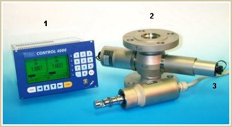
- Converter (transmitter)
- Sensor - in-line flow-through or
insertion-type probe sensor bodies equipped with
light source and detector assemblies.
- Cableset - special high-grade shielded
cable assemblies interconnecting the sensor to the
converter.
Within the sensor, light from the light source is
focused and sent into the process stream. The emerging
light that has penetrated the process medium is
precisely filtered then measured on the opposing side by
high-precision absorption or scatter-light detectors.
The resultant photocurrents from the process sensor are
precisely amplified, analyzed and converted by the
transmitter and then sent to the plant's process control
system providing real-time measurements in virtually any
unit of measure.
PRINCIPLES OF MEASUREMENT
optek process photometers utilize two principles which
are based on the interaction of light that is passed
through process liquids and gases:
-
Light Absorption
-
Light Scattering
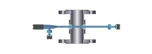
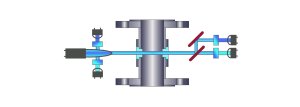
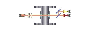
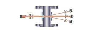
For an example of these
two principles, the illustrations below show cutaway
views of typical flanged in-line type sensors. Please
note on the left side of each illustration a light
source, apertures and focusing optics are depicted as
sending light through the process medium via two windows
installed in the in-line sensor body. The light travels
through the process medium and is detected on the
opposing side by a variety of optical configurations.
Each of the illustrations
depict the orientation of photo detectors and optics in
relation to the incident light source on the opposing
side of the sensor body. Each design has specific
applications and benefits for the measurement of liquids
and gases in-line and in real time.
UV -
Ultraviolet Light Absorption
Single
Channel Light Absorption
(single detector, with lamp reference detector)
Dual Channel Light Absorption
(beam splitter, dual detectors and dual lamp reference
detectors)
VIS
/ NIR - Visible and Near Infrared Light Absorption
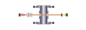
Single Channel Light Absorption (single
detector)
Dual
Channel Light Absorption (beam splitter, two
detectors)
Scattered-Light - 11° Forward
Dual Beam Light Scatter (one reference
detector and eight 11° scatter detectors)
optek's Spectral Range of Measurement
Wavelengths: 254 nm (Ultra Violet) to 1100 nm (Low Near
Infrared)

The complete line of
optek process photometers use two superior grade light
sources and a variety of precision filters and photo
components. The wide selection of optical components
allows optek to configure a process analyzer to measure
within a specific portion of the electromagnetic
spectrum to serve a host of specific process measuring
applications:
optek light
Sources:
Low Pressure Mercury: Measuring Range: 254 to
340 nm
Full Spectrum Tungsten:
Measuring Range: 380 to 1100 nm
Lambert-Beer Law
Lambert Beer’s
law is a mathematical means of expressing how light is
absorbed by matter. The law states that the amount of
light emerging from a sample is diminished by three
physical phenomena:
- The amount of
absorbing material in its pathlength (concentration)
- The distance the
light must travel through the sample (optical
pathlength OPL)
- The probability that
the photon of that particular wavelength will be
absorbed by the material (absorptivity or extinction
coefficient)
This relationship may be
expressed as:
A = ebc
Where: A= absorbance; e =
molar extinction coefficient; b = pathlength in cm; and
c = molar concentration.
Transmittance
As a beam of light passes
through an absorbing medium, the amount of light
absorbed in any unit volume is proportional to the
intensity of incident light times the absorption
coefficient. Consequently, the intensity of an incident
beam drops exponentially as it passes through the
absorber. This relationship when expressed as Lambert’s
Law is:
T = 10-acx or T
= 10-A
Where T = transmittance;
a = absorption coefficient; c = molar concentration of
the absorber and x = pathlength in cm
In a simplified approach,
the transmittance can be expressed as the intensity of
the incident radiation, Io which is ratioed to the light
emerging from the sample, I. The ratio I/Io is referred
to as transmittance or simply T.
Absorption
Transmittance can be
plotted against the concentration, but the relationship
is not linear. The negative log 10 of the transmittance
is, however, linear with the concentration.
Therefore, absorption is
measured as:
A = -log 10 (I/Io) or A = -log 10
(T) |

